diff options
Diffstat (limited to 'docs/architecture.md')
| -rw-r--r-- | docs/architecture.md | 54 |
1 files changed, 36 insertions, 18 deletions
diff --git a/docs/architecture.md b/docs/architecture.md index 8daa7e4..0610d90 100644 --- a/docs/architecture.md +++ b/docs/architecture.md @@ -11,47 +11,52 @@ Important notes: # Game controllers ## Input + The playable character has 4 actions that it can perform: -- movement on the x-axis (left / right) -- jump -- ability / use -To perform these action there will be 4 buttons for the user to use. + +- horizontal movement +- aiming +- jump +- ability / use + +To perform these action there will be 6 buttons for the user to use. A joystick is not needed for the movement because the movement is not complex, so button fulfill this. The layout will be as follows: -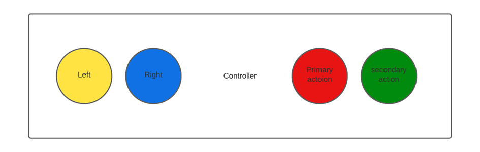 +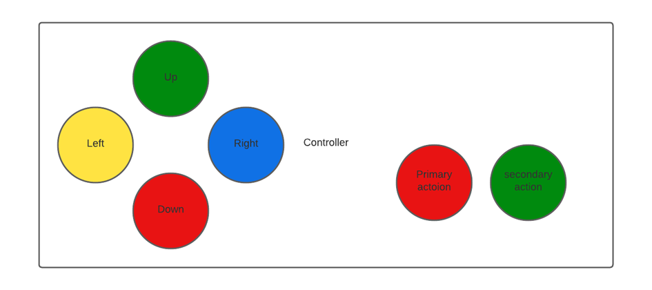 ## Input handling: + The hardware consist out of a microcontroller and a FPGA. The microcontroller will process the game logic. For this reason the input will be handled by the microcontroller as this will improve playability (stated in research). -The controller will have four buttons, so 4 data pins are needed on the microcontroller plus a ground and 3.3V or 5V pin. -In total there are 6 pins needed. -If the game is going to be played by 2 person, there are 4 more data pins needed so 8 data pins for both controllers. +The controller will have six buttons, so six data pins are needed on the microcontroller plus a ground and 3.3V or 5V pin. +In total there are eight pins needed. +If the game is going to be played by 2 persons, there are six more data pins needed so 8 data pins for both controllers. For data transfer between STM32 and FPGA there are 4 pins needed at maximum (SPI for instance). The STM32 will be used and most STM32 boards have enough I/O pins for our needs. The STM32 F030 and F091 provided by Avans both have 15 digital pins and 6 analog pins. The buttons will be connected as follows: -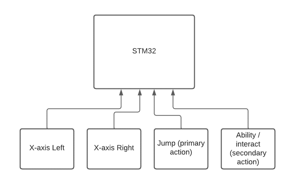 +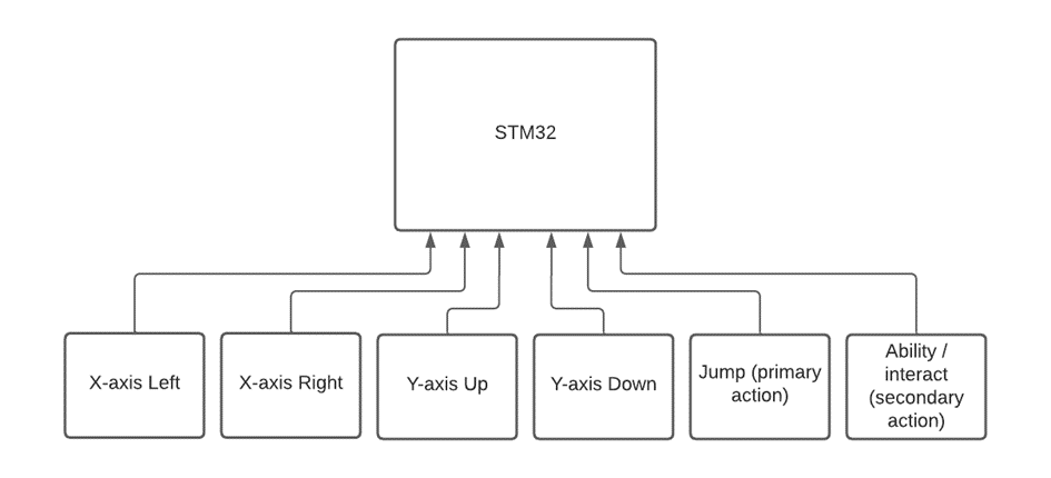 To implement the input in the game, the input should be checked at the start of each game cycle. In this case there are no interrupts needed. # STM32 software + The game engine will be designed to support 2D games. The engine will use a state machine to manage game states and transitions between them. The state machine will be implemented using a finite state machine (FSM) design pattern. The engine will also include support for handling user input, game logic, and sound. FSM is a useful tool for managing game states and transitions. A game can have many different states, such as a title screen, a level selection screen, a loading screen, and various gameplay states. Each state represents a particular configuration of the game, with different sets of variables, objects, and logic The state machine will be designed with the following states: -1. Initialization: The initialization state will be responsible for initializing all game-related variables and subsystems, including the FPGA-based picture processing unit. -2. Title Screen: The title screen state will display the game's title screen and wait for user input to start the game or access the options menu. -3. Options: The options state will allow the user to configure game settings, such as sound and graphics options. -4. Game Play: The game play state will be responsible for running the game logic and updating the game state. -5. Game Over: The game over state will display the game over screen and wait for user input to restart the game or return to the title screen. - +1. Initialization: The initialization state will be responsible for initializing all game-related variables and subsystems, including the FPGA-based picture processing unit. +2. Title Screen: The title screen state will display the game's title screen and wait for user input to start the game or access the options menu. +3. Options: The options state will allow the user to configure game settings, such as sound and graphics options. +4. Game Play: The game play state will be responsible for running the game logic and updating the game state. +5. Game Over: The game over state will display the game over screen and wait for user input to restart the game or return to the title screen. # PPU @@ -256,9 +261,6 @@ Important notes: --> -[nesppuspecs]: https://www.copetti.org/writings/consoles/nes/ -[nesppudocs]: https://www.nesdev.org/wiki/PPU_programmer_reference -[nesppupinout]: https://www.nesdev.org/wiki/PPU_pinout [custompputimings]: https://docs.google.com/spreadsheets/d/1MU6K4c4PtMR_JXIpc3I0ZJdLZNnoFO7G2P3olCz6LSc # APU @@ -274,6 +276,7 @@ The Audio Processing Unit (APU) is programmed on the FPGA, here it will produce These signals will be generated using PWM, this allows a digital signal to act as an analog signal. Using this method it is theoretically possible to create all of the aforementioned signals.  + This figure shows an example signal (in blue), created by the FPGA. and the corresponding analog signal (in red). In order to generate a audio signal from a note, we need a few things: @@ -298,3 +301,18 @@ for (i = 0; i < toneLength; i++){ } ``` This output can then be converted to a PWM signal using known methods or existing solutions as described in the beginning of this chapter. + +# Level design + +To create sprites the program to be used is aseprite, aseprite exports their +sprite palette and puts them in our 2d map editor. For creating 2d levels were +using Tiled as our 2d map editor. With this software, we can create and export +our maps with our preferred technique. Indexed tilemaps are the technique we’re +using to export our levels from the microcontroller to the FPGA. + + + +To index tiles from the tilemap, 10 bits will be used for both the foreground +and background layers of the PPU. This means that the global tilemap can fit up +to 1024 tiles in total, each being 16x16 pixels (the example uses 4x4 tiles for +illustration purposes). |