diff options
Diffstat (limited to 'docs/architecture.md')
| -rw-r--r-- | docs/architecture.md | 24 |
1 files changed, 19 insertions, 5 deletions
diff --git a/docs/architecture.md b/docs/architecture.md index 3452862..1ae4198 100644 --- a/docs/architecture.md +++ b/docs/architecture.md @@ -30,14 +30,14 @@ For this reason the input will be handled by the microcontroller as this will im The controller will have four buttons, so 4 data pins are needed on the microcontroller plus a ground and 3.3V or 5V pin. In total there are 6 pins needed. If the game is going to be played by 2 person, there are 4 more data pins needed so 8 data pins for both controllers. -For data transfer between STM32 and FPHA there are 4 pins needed at maximum (SPI for instance). +For data transfer between STM32 and FPGA there are 4 pins needed at maximum (SPI for instance). The STM32 will be used and most STM32 boards have enough I/O pins for our needs. -The STM32 F030 and F091 provided by AVANS both have 15 digital pins and 6 analog pins. +The STM32 F030 and F091 provided by Avans both have 15 digital pins and 6 analog pins. The buttons will be connected as follows: 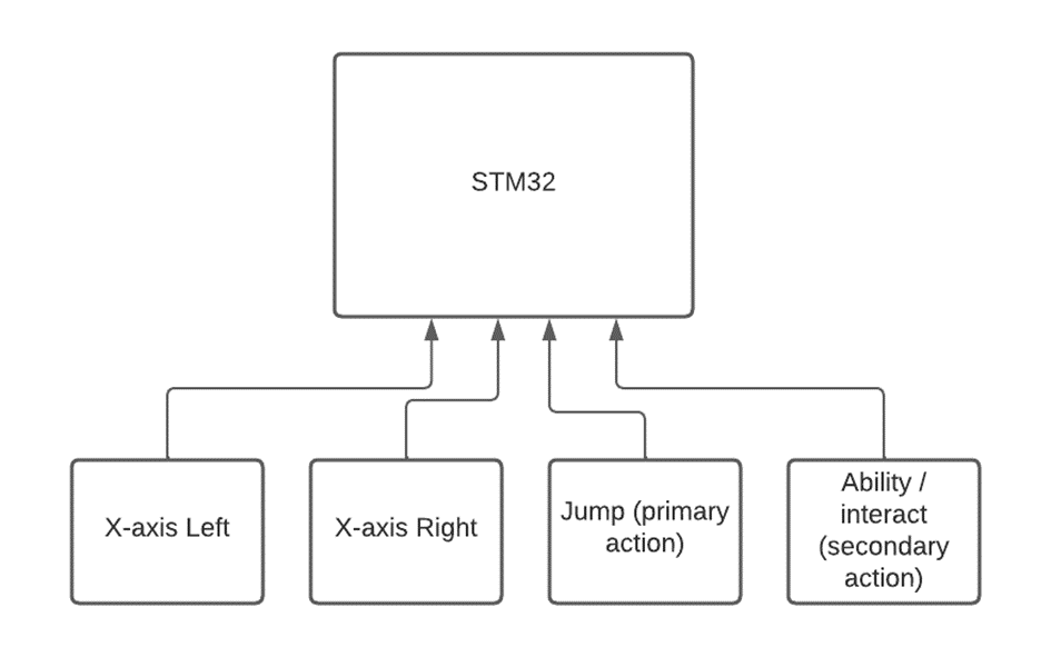 -To implement the input in the game, the input should be ckecked at the start of each game cycle. In this case there are no interupts needed. +To implement the input in the game, the input should be checked at the start of each game cycle. In this case there are no interrupts needed. # STM32 software The game engine will be designed to support 2D games. The engine will use a state machine to manage game states and transitions between them. The state machine will be implemented using a finite state machine (FSM) design pattern. The engine will also include support for handling user input, game logic, and sound. @@ -99,9 +99,9 @@ Notable differences: - 8 total palettes, with 8 colors each More colors is better. Increasing the total palette count is a very memory - intensive operation, while increaing the palette color count is likely slower + intensive operation, while increasing the palette color count is likely slower when looking up color values for each pixel on real hardware. -- Sprites can be positioned paritally off-screen on all screen edges using only +- Sprites can be positioned partially off-screen on all screen edges using only the offset bits in the FAM register The NES has a separate PPUMASK register to control special color effects, and @@ -263,3 +263,17 @@ Important notes: # APU +The Audio Processing Unit (APU) is programmed on the FPGA, here it will produce different signals on the audio output. These signals come in a few forms, as listed below. + +- triangle waves +- square waves +- sine waves +- sawtooth waves +- random noise + +These signals will be generated using PWM, this allows a digital signal to act as an analog signal. Using this method it is theoretically possible to create all of the aforementioned signals. + + +This figure shows an example signal (in blue), created by the FPGA. and the corresponding analog signal (in red). + + |