diff options
| author | lonkaars <loek@pipeframe.xyz> | 2023-02-15 21:23:07 +0100 |
|---|---|---|
| committer | lonkaars <loek@pipeframe.xyz> | 2023-02-15 21:23:07 +0100 |
| commit | 0730ad350a3a58de3a60ebe00e141a66875c5c33 (patch) | |
| tree | ae540b0b0af9964e0dde82d12a866becc691a69a /docs/architecture.md | |
| parent | 533ac91079738dc4b957c836f92113fee3b2c8ce (diff) | |
merge #11
Diffstat (limited to 'docs/architecture.md')
| -rw-r--r-- | docs/architecture.md | 10 |
1 files changed, 5 insertions, 5 deletions
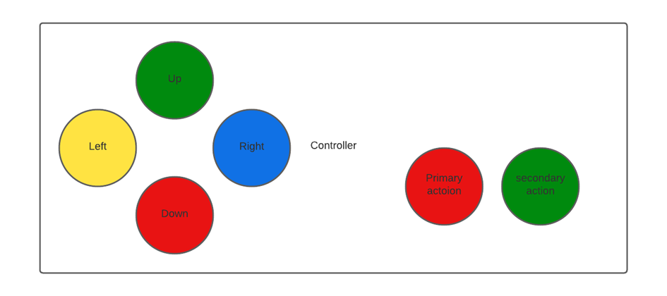
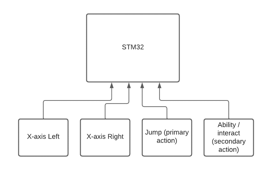
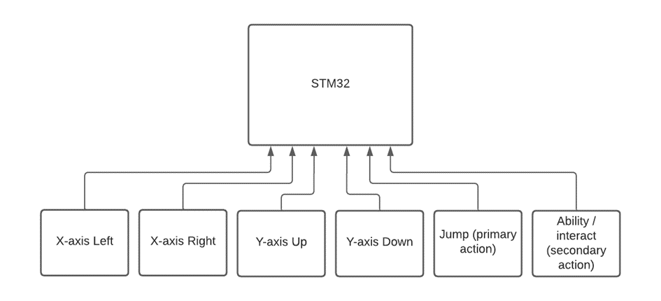
diff --git a/docs/architecture.md b/docs/architecture.md index 9c1e5f5..c1a2a95 100644 --- a/docs/architecture.md +++ b/docs/architecture.md @@ -24,7 +24,7 @@ To perform these action there will be 6 buttons for the user to use. A joystick is not needed for the movement because the movement is not complex, so button fulfill this. The layout will be as follows: - + ## Input handling: @@ -32,15 +32,15 @@ The hardware consist out of a microcontroller and a FPGA. The microcontroller will process the game logic. For this reason the input will be handled by the microcontroller as this will improve playability (stated in research). -The controller will have four buttons, so 4 data pins are needed on the microcontroller plus a ground and 3.3V or 5V pin. -In total there are 6 pins needed. -If the game is going to be played by 2 person, there are 4 more data pins needed so 8 data pins for both controllers. +The controller will have six buttons, so six data pins are needed on the microcontroller plus a ground and 3.3V or 5V pin. +In total there are eight pins needed. +If the game is going to be played by 2 persons, there are six more data pins needed so 8 data pins for both controllers. For data transfer between STM32 and FPGA there are 4 pins needed at maximum (SPI for instance). The STM32 will be used and most STM32 boards have enough I/O pins for our needs. The STM32 F030 and F091 provided by Avans both have 15 digital pins and 6 analog pins. The buttons will be connected as follows: - + To implement the input in the game, the input should be checked at the start of each game cycle. In this case there are no interrupts needed. |